V-Cut Breaking vs Manual Snapping: Which Depaneling Method Actually Protects Your LED PCB Yield?
V-Cut Breaking vs Manual Snapping: Which Depaneling Method Actually Protects Your LED PCB Yield?
You run 200 MCPCB (Metal Core PCB) panels through a full SMT line — solder paste printing, Pick and Place component mounting, Reflow Oven profiling, AOI inspection. Every step is measured, controlled, and optimized. Then those panels reach the depaneling station, and one operator snaps them apart by hand over a table edge.
This is not an unusual scene in LED lighting factories across the Pearl River Delta. The contrast between precision SMT assembly and manual separation is striking. And it raises a question that few factories formally investigate: how many of your "component defects" or "solder joint failures" are actually depaneling damage?
The Hidden Gap Between FR4 and Aluminum-Core PCB Depaneling
Standard FR4 PCBs have predictable mechanical behavior at the V-groove score line. They snap cleanly when the V-groove depth is correct (typically one-third of board thickness on each side). The glass-epoxy composite fractures along a predictable path with minimal stress transfer to nearby components.
PCB V-Groove Separator for LED Panel Depaneling
MCPCBs are fundamentally different. The aluminum substrate adds thermal management capability — critical for LED applications where junction temperature directly affects lumen maintenance and service life. But that same aluminum layer makes depaneling unpredictable:
- The aluminum core does not fracture like FR4. It bends before it breaks.
- Manual bending concentrates stress at the component side of the score line, not the V-groove.
- SMD components near the board edge absorb tensile stress during bending.
- Micro-cracks in the aluminum substrate at the separation edge can propagate during thermal cycling (the repeated heating and cooling that LED modules experience in operation).
Post-depaneling visual defect rates for manually separated MCPCBs range from 3% to 12% in typical LED lighting EMS production. Most of these defects — edge cracks, lifted pads, fractured solder joints near the board edge — are initially recorded as "component damage" or "solder defect" during AOI. The depaneling station is rarely flagged as the root cause.
The problem is compounded by measurement. Most LED factories measure AOI yield at the SMT line exit, before depaneling. By the time boards reach functional test, depaneling damage is already counted as a "downstream failure" with no attribution back to the separation step. The cost is real but invisible in the data.
How Dedicated MCPCB Depaneling Eliminates the Two Failure Modes
A purpose-built depaneling machine for aluminum-core PCBs addresses the problem from two angles: stress control and repeatability.

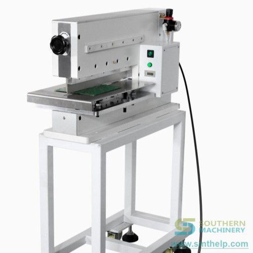
Dedicated LED MCPCB Separator for Clean Board Edge Separation
Stress control. Instead of relying on human judgment to apply the right bending force at the right angle, a machine applies breaking pressure in a controlled, perpendicular plane to the score line. The S-D601 LED MCPCB Separator from Southern Machinery, for example, uses adjustable breaking pressure calibrated to board thickness — from 0.6mm for standard LED bulb boards to 3.0mm for high-power automotive LED modules. The breaking mechanism supports the board on both sides of the V-groove, isolating the separation force to the score line and preventing stress from reaching SMD components.
Repeatability. Every board sees the same breaking cycle. The alignment guides, adjustable stops, and PLC-controlled cycle sequence mean the separation force is identical across 1,000 panels in a shift. For a 300x300mm street light MCPCB panel with 24 individual units, consistent separation quality across all 24 score lines is difficult to achieve manually beyond the first 10-15 panels. The operator's technique drifts with fatigue. A machine does not.
The S-D601 is SMEMA-compatible and can be configured inline between Reflow Oven outfeed and the next processing station. Positioning accuracy of +/-0.05mm ensures the score line aligns correctly with the breaking blade on every cycle. For factories that process mixed panel sizes, the quick-change tooling adjusts to different layouts in under five minutes.
When V-Cut Breaking Works — and When It Does Not
Dedicated MCPCB depaneling is not a universal solution. It addresses a specific range of board types and volumes. Understanding the boundaries helps factories decide where to invest.
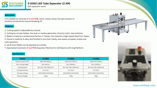
Southern Machinery Separator Product Line Brochure
V-cut breaking works well for:
- MCPCB thickness 0.6mm to 3.0mm
- Panel sizes from 50x50mm to 600x600mm
- Boards with standard V-groove scoring (60-90 degree angle, 0.3-0.5mm residual thickness)
- Production volumes above 500 panels per shift (where operator consistency becomes a factor)
- Aluminum-core and FR4 panels on the same line (the S-D601 handles both)
Routing (not V-cut breaking) is required for:
- Board thickness below 0.6mm (too thin for controlled V-groove fracture)
- Irregular board shapes without straight V-groove lines
- Flexible PCBs (FPC) that bend rather than fracture
- Panels with components very close to the score line (routing removes material without mechanical stress)
The economic case is straightforward. A dedicated depaneling machine represents a fraction of the investment in a single Pick and Place system. For factories that currently lose 5-10 MCPCB panels per shift to edge cracking and rework, the payback period is typically measured in months, not years. The savings come from three sources: reduced scrap (direct material cost), reduced rework labor (operators who hand-repair cracked boards), and reduced field failure risk (micro-cracks that pass visual inspection but fail after 500 hours of thermal cycling).
The 5-Minute MCPCB Depaneling Audit
Most LED factories do not have a formal metric for depaneling quality. The following exercise takes five minutes and will tell you whether your depaneling station deserves attention.
- Take 50 consecutively separated MCPCB units from your current production.
- Inspect each board edge under 10x magnification. Look for: visible cracking at the score line, lifted or fractured solder joints within 5mm of the board edge, and aluminum substrate deformation at the separation point.
- Count the number of boards with any of these defects.
- Multiply by your daily panel count and the average board value.
Example: if 8 out of 50 boards show edge defects (16%), and your line runs 200 panels per day at USD 1.50 per board, the daily loss is 200 x 0.16 x 1.50 = USD 48. Over 300 production days, that is USD 14,400 in directly observable scrap — before accounting for field returns and rework labor.
This number is usually higher than most plant managers estimate because edge cracks that are cosmetic today can become electrical failures during thermal cycling. The LED industry's transition to higher power densities and smaller board sizes makes the problem worse: more heat per square millimeter means more thermal expansion stress at an already compromised board edge.
MCPCB Depaneling Yield Loss Calculator
Enter your actual production numbers below and calculate your monthly and annual loss from manual depaneling defects.
Compare the annual loss against the investment required for a dedicated depaneling machine. The gap is often smaller than expected.
Use this calculator to run the audit with your actual numbers. A data-driven answer to the question "V-cut breaking vs manual snapping" removes the guesswork and lets you allocate capital based on actual yield improvement potential.