Your Wave Soldering Line Has a Hidden Bottleneck: The Manual Insertion Station
Your Wave Soldering Line Has a Hidden Bottleneck: The Manual Insertion Station
Most factory dashboards track Wave Soldering machine parameters with precision. Conveyor speed, preheat zone temperature, flux flow rate, solder pot temperature — every variable is logged, trended, and reviewed. If the Wave Soldering conveyor is set to 1800 mm/min, the assumption is clear: the machine is running at capacity.
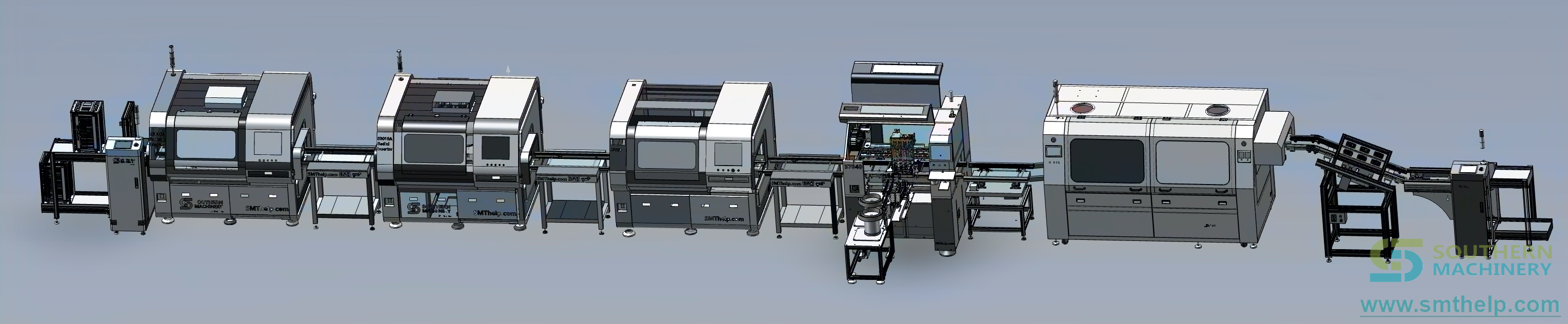
THT auto insertion & Wave Soldering line
But is it?
Walk onto any THT line where manual insertion feeds a Wave Soldering machine, and you will likely see a different picture. Boards accumulate in front of the Wave Soldering station not because the machine is slow, but because the upstream insertion process cannot keep up. The Wave Soldering machine cycles, waits, and cycles again. The dashboard shows uptime. What it does not show is how much of that uptime is productive and how much is waiting.
This gap — between machine-rated throughput and actual line throughput — is one of the most common and least measured capacity losses in THT assembly. And it almost always traces back to the same root cause: the manual insertion station.
The Hidden Gap
To understand the scale of the mismatch, it helps to look at the numbers.
A single manual insertion operator typically places 300-800 CPH, depending on component type, board complexity, and operator experience. For a typical THT PCB with 60 through-hole components — a mix of capacitors, resistors, connectors, and LEDs — one operator produces roughly 5 to 13 boards per hour.
A mid-size Wave Soldering machine such as the S-WS350B or S-WS450 runs at 300-1800 mm/min conveyor speed. For a 300mm-long PCB with typical inter-board spacing, that translates to roughly 45 to 270 boards per hour. Even at the conservative end of conveyor speed, the Wave Soldering machine can process 3 to 16 times more boards per hour than the manual insertion station can supply.
This mismatch compounds across shifts. A three-shift operation with two manual insertion operators per shift produces roughly 10,000 to 12,000 inserted boards per month. The Wave Soldering machine behind them is capable of handling several times that volume. The lost capacity is not a machine problem. It is a line balance problem that starts at the insertion station.
The costs go beyond lost throughput. Manual insertion rework rates typically range from 2% to 5%, driven by missing components, reversed polarity, floating leads, and bent pins. Each defect that reaches Wave Soldering requires post-solder touch-up, adds inspection time, and increases the risk of thermal damage from repeat soldering. Inconsistent insertion quality between operators and between shifts adds variability that makes process control difficult.
Pre-Wave Auto Insertion Bridges the Gap
The logic for placing auto insertion machines upstream of Wave Soldering is straightforward: if the insertion bottleneck is eliminated, the Wave Soldering line runs at its natural throughput.
Auto insertion machines handle components at speeds that match or exceed Wave Soldering capability. A radial insertion machine such as Southern Machinery's S-3010B operates at 13,000 CPH in production — roughly 20 times faster than a manual operator. Its four-span capability (2.5, 5.0, 7.5, and 10.0mm) covers the most common radial lead components: capacitors, transistors, LEDs, and key switches. An axial insertion machine such as the S4000 handles resistors and diodes at 20,000 CPH.
In a typical pre-Wave Soldering configuration, three to four auto insertion machines — radial for capacitors and transistors, axial for resistors and diodes, and an odd-form machine such as the S-70LD for transformers and connectors — are arranged in sequence, loaded by a single operator. The combined output of these machines supplies the Wave Soldering line at its rated speed, eliminating the board accumulation gap.
Wave Soldering machine
The quality difference is measurable. Auto insertion machines use vision calibration for PCB fiducial alignment and servo-driven insertion heads with clinch control. The insertion force is consistent cycle to cycle. Clinch angles are programmable between 10 and 35 degrees with 1.5-2.2mm clinch length, ensuring components remain seated through the Wave Soldering process. Rework rates on auto-inserted boards are typically below 0.5%, compared to 2-5% for manual insertion.
One operator can manage three to four auto insertion machines because the machines handle the repetitive work. The operator's role shifts from component placement to machine loading, tape splicing, and quality monitoring. This is a structural change in how labor is deployed, not just a speed improvement.
Context & Exceptions
Pre-Wave Soldering auto insertion makes economic sense under certain conditions. The clearest case is mid-to-high-volume production of standard PCBAs — boards with 20+ through-hole components per PCB, stable product designs, and production volumes above 500 PCBs per month. Power supply boards, LED lighting PCBs, and appliance control boards are typical examples where the component mix is dominated by standard radial and axial parts.
The case is weaker for ultra-high-mix, low-volume production — under 200 PCBs per month with frequent changeovers — or for boards where 80% or more of the components are surface-mount devices handled by a Pick and Place machine upstream. In these scenarios, the cost of setup and programming for auto insertion may outweigh the throughput benefit.
The retrofit path is relevant here. Auto insertion machines are typically standalone units that can be added to existing THT lines without replacing Wave Soldering equipment. The S-3010B, for instance, is an offline machine with its own conveyor interface, requiring only 220V single-phase power and compressed air at 0.6 MPa. Integration with existing S-WS350B or S-WS450 Wave Soldering lines is a conveyor extension, not a system replacement.
The payback range is 12 to 24 months, depending on labor cost, product volume, and the number of shifts. In high-labor-cost regions or three-shift operations, the payback tends toward the shorter end. The calculation starts with the same gap measurement described above.
The 5-Minute Line Balance Check
Here is a practical exercise that takes about five minutes. Walk to your Wave Soldering line during a production run. Count the PCBs waiting on the conveyor before the flux sprayer. Multiply by the board cycle time. This tells you how many minutes of Wave Soldering capacity are lost per batch due to upstream starvation.
Then measure the gap more precisely. For your most common board type, calculate:
- Board length (mm) / Wave Soldering conveyor speed (mm/min) = theoretical boards per minute
- Available operator hours per shift / minutes per board (manual insertion) = actual boards per minute
The difference is the hidden capacity loss.
Use the calculator below to quantify your line balance gap. Enter your parameters and click Calculate.
THT Line Balance Calculator
Enter your line parameters and click Calculate
| PCB length (mm) | mm |
| Wave Soldering conveyor speed | mm/min |
| THT components per PCB | components |
| Manual insertion operators per shift | |
| Manual insertion speed per operator | CPH |
| Shifts per day | |
| Operating days per month |
Why this matters for future investment decisions: if your Wave Soldering line is running at 50-60% of its rated throughput because of upstream insertion starvation, the right fix is often not another Wave Soldering machine. It is an auto insertion station in front of the one you already own.
If you ran the calculator above and found a gap larger than 30%, you have identified a capacity improvement opportunity that requires no new Wave Soldering equipment. The next step is a quick feasibility review of your board mix to see which components can be auto-inserted and what machine configuration fits your line.