
The 20,000 CPH Gap: What Axial Component Insertion Means for Power Supply PCB Assembly
The 20,000 CPH Gap: What Axial Component Insertion Means for Power Supply PCB Assembly
When a power supply PCB carries 40 axial resistors and diodes, the math is straightforward. At 300 components per hour per operator — a realistic sustained rate for through-hole insertion — that single board consumes about 8 minutes of labor at the manual station. Run a batch of 500 boards, and you have committed 67 operator-hours to just one component type.
Now consider the same board on an axial auto insertion machine running at 20,000 CPH. The same 40 axial components take 7 seconds. The batch of 500 boards finishes in under one hour. One machine, no operator fatigue, no polarity errors passed downstream.
This is the 20,000 CPH gap. It is not a theoretical benchmark. It is the difference between a THT line that scales with volume and one that scales only with headcount.
The Hidden Cost Structure of Manual Axial Insertion
Most power supply factories already know their manual insertion cost per board. What is less visible is how that cost behaves as volume changes.
Manual insertion cost is strictly linear with volume. Double the batch size, double the operator hours. The per-unit labor cost does not decrease. If a factory runs two shifts of axial insertion with 3 operators per shift, the annual labor cost at a blended rate of USD $5-8 per hour in the PRD region reaches USD $60,000-96,000 per year for just the axial station. This calculation excludes turnover, training, and the defect cost downstream.
The defect cost is where the hidden expense compounds. Even in a well-managed manual station, insertion defects typically run 2-5% across production. The most common failure modes:
- Polarity reversals on diodes — the most frequent and hardest to catch visually
- Value mix-ups from component bin confusion during high-volume runs
- Bent leads that escape visual inspection and cause open joints at Wave Soldering
- Loose clinching that produces component float during wave contact
Each defect that passes through to Wave Soldering requires touch-up or rework. A single axial resistor that fails wave contact may cost USD $0.50-2.00 to repair depending on access and board density. On a board with 40 axial components and a 3% manual error rate, that board carries roughly one defect on average. Over a 100,000-board annual run, that is 120,000 defective insertions — each one a cost event that adds no value to the product.
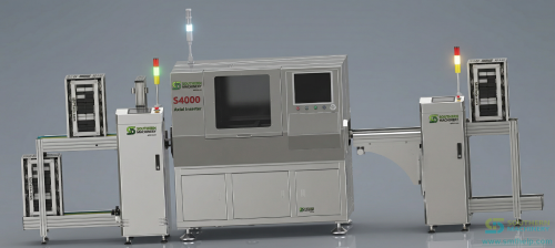
S4000 Axial Auto Insertion Machine with PCB loader
How Axial Auto Insertion Changes the Economics
An axial auto insertion machine replaces the manual station with a fully automated process. The mechanism is straightforward: axial components on tape-and-reel are fed into the machine, the leads are formed to match PCB hole spacing, components are inserted with vision-guided accuracy, and clinching secures them for the Wave Soldering process that follows.
The S4000 from Southern Machinery is one example of this class of machine. Its specifications illustrate the current price-performance point for Shenzhen-manufactured SMT/THT equipment:
- Throughput: 20,000 CPH
- Component capacity: 100+ stations in a rotating table design
- Lead forming: Adjustable to match PCB hole pitch
- Control: EtherCAT bus with MES-ready interface
- Clinch: Programmable angle and length for secure retention
- Vision alignment: Confirms polarity and lead condition before each insertion
The key operational difference is not just speed. It is consistency. Every component sees the same insertion force, the same clinch geometry, the same cycle time. The machine does not slow down at hour 7 of a shift. It does not misread a resistor band or confuse one diode type for another. Vision alignment catches bent leads before insertion — the machine flags the fault rather than inserting it and passing the problem to Wave Soldering.
In practice, one operator can manage 3-4 axial insertion machines. The labor ratio shifts from 3 operators per shift to 1 operator per 4 machines. The defect rate on the automated station drops to under 0.5%, with most remaining faults traced to upstream PCB hole tolerance rather than insertion accuracy.
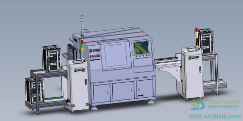
S4000 Axial Insertion Machine with 10 feeders and PCB loader
Where This Makes Sense and Where It Does Not
Auto axial insertion is not a universal replacement for all THT assembly. The economics depend on volume, product mix, and line configuration.
It fits well when:
- The BOM includes 20 or more axial components per board
- Annual volume exceeds 50,000 boards
- The product mix is stable enough that feeder setup changes are infrequent
- The factory runs two or three shifts and wants to reduce night-shift hiring dependency
It fits less well when:
- Batch sizes are under 500 boards with frequent changeovers
- Axial components account for fewer than 5-8 positions per board
- The product mix changes weekly and the line needs constant reprogramming
- Capital for the machine needs to be recovered in under 12 months at current local labor rates
For factories in the middle range, a retrofit approach can work: adding one axial insertion machine to the existing THT line without replacing other stations. The manual station is reassigned to odd-form components that are harder to automate. This keeps capital deployment focused on the highest-ROI segment of the line.
The 5-Minute Staffing Audit
To determine whether axial auto insertion makes economic sense for your line, start with five numbers:
- Number of axial components (resistors, diodes, jumpers) per PCB
- Average daily board volume
- Number of operators at the manual axial insertion station per shift
- Number of shifts per day
- Blended operator cost per hour (including benefits, housing, and turnover)
With these five inputs, you can calculate the annual labor cost of manual axial insertion and compare it to machine amortization. A single machine running at 20,000 CPH can process approximately 2,000-3,500 boards per shift depending on board complexity and changeover frequency (assuming 40 axial components per board), leaving capacity headroom for growth.
The formula is simple: operators per shift times shifts per day gives total daily operator-hours. Multiply by 250 working days and the hourly rate to get the annual labor cost. Compare that to the machine's annual amortization over a 3-5 year equipment life.
Download Resource Download Axial Insertion Staffing Audit Worksheet (XLSX — 2 Sheets)
A Final Observation
The 20,000 CPH gap is not a sales proposition. It is a structural reality of THT assembly in 2026. Manual axial insertion scales with headcount. Machine axial insertion scales with throughput. For any factory running axial components at volume, the two cost curves diverge within the first year.
The question is not whether the gap exists. It is whether your current line is on the right side of it.